Showing posts with label Steampunk. Show all posts

Wednesday, October 10, 2012

A Simple Pump: The Idea

The Premise

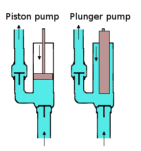
Fig. 1: A Piston Pump (left). Wikipedia
Atlanta is hot in the summer, so have a cool drink can become very necessary (especially when wearing a costume at Dragon*Con). Now, a steampunk would not be caught carrying around a CamelBak, and a canteen, while practical, is a bit boring. Why not use a pump to bring fluid from my backpack to a dispenser and maybe find a way to cool it in the process.

I want to create a piston-cylinder device (see Figure 1) to pump fluid through a cooling medium and out of a dispenser. The pump will also be powered by my flywheel. After, a bit of searching, I think I have come up with a simple, easy to build pump.

The Proposed Method

My current idea is to take an empty wine bottle, lop off the bottom, machine an airtight piston to fit inside the bottle, then run the piston using a crank arm. Figure 2 is a conceptual drawing of the idea.

Figure 2: Conceptual Sketch of A Pump.
Bottle(Green), Piston(Black),
Crank Arms(Blue), Liquid(Teal?)
As the left-side arm rotates, the piston will create pressure, forcing the fluid out of the mouth of the bottle to the right. It should also be reversible, in order to draw the fluid back into the bottle, for storage.

To cut the bottom off the bottle, I will try this tutorial from GreenPowerScience.com. They get a bit long winded in the video, but thanks to the Wadsworth Constant, you can use this link instead and skip over the fluff.

As for the piston, I have not decided on how to make that yet. I am stuck between two different options:

  1. Machine metal into shape, and use some rubber grommets to create the seal
  2. Use a 3D printer to create a piston out of ABS, then machine it to fit

I am leaning more toward #2, but then again, I just really want a Solidoodle.

The interface with the flywheel is probably going to be a combination of a pulley and belt connected to the flywheel shaft, and a worm drive connected to the crank arm. There will also need to be a reversal option available, but that might take the form of a crossed belt drive.

The Concerns

I am concerned about efficiency with this design. The input is coming from a very high rotational velocity(the flywheel) and trying to convert it to a very slow linear velocity(the crank arm). I have a feeling that this mechanism will be more of a metering device than an actual pump. It will take a bit more thought to understand how this system will function.

I will be creating another post about the math behind the pump, after a few considerations for placement and orientation. I primarily wanted to get this information out of my head.

Wednesday, September 26, 2012

An Introduction to Flywheel Energy Storage Principles

Editorial Note: This is a very math heavy post. They won't all be this way, although it is a very engineering heavy project. Once I get to the prototyping phase, things should settle down a bit. Also, if the math fonts look bad, right click and set the math renderer to SVG.

Preliminary Flywheel Sizing

Before I get too far into the design of my Dragon*Con costume, I need to do a bit of a study in feasibility. The biggest unknown for my costume is: How big of a flywheel will I need to power my contraptions? In order to start answering this, I need an approximation. Since I want to be able to charge my cell phone using the energy stored in the flywheel, I figured that would be a good place to start. The charger explicitly states the output and barring any gross inefficiencies in any of the electrical circuits, I have calculated the information below.

Energy Needs

At the peak, my cell phone charger's output is 5VDC @ 1A. Therefore the energy required to run the charger for 1hr is:

$$\begin{aligned}
E_{req.} &= 5VDC \cdot 1A \cdot 1hr\\
E_{req.} &= 5watt \mbox{-} hours
\end{aligned}$$

5watt-hours does not seem like much.

Flywheel Energy Storage Equations

The rotational energy stored in a flywheel is calculated using the following equation:

\[ E_{k} = \frac{1}{2} I \omega^{2} \]
Where:
  • \(E_{k}\) is the rotational energy, in Joules.
  • \(I\) is the mass moment of inertia, in \(kg \cdot m^{2}\).
  • \(\omega\) is the angular velocity, in radians per second.
Since these calculations are primarily to determine viability of having a spinning ~5lb mass of steel on my back, I decided to assume that the mass moment of inertia could be approximated using the equation for a thick-walled empty cylinder:

\[ I = \frac{1}{2} m ( r_{external}^{2} + r_{internal}^{2} ) \]
Where:
  • \(m\) is the mass, in kilograms.
  • The \(r\)'s are radii, in meters.

The Exciting Conclusion

Since I have an idea of how large of a diameter I want my flywheel to be, then my unknown variable becomes \(\omega\). In order to find \(\omega\), I started by defining my variables:

\[\begin{aligned}
r_{internal} &= 0.1143 m ( 4.5in )\\
r_{external} &= 0.1270 m ( 5.0in )\\
M &= 2.268kg( 5lb )\\
E_{k} &= 1800J( 5watt \mbox{-} hours )\\
\end{aligned}\]

Then, substituting the equation for the mass moment of inertia into the rotational energy equation, we get:

\[\begin{aligned}
E_{k} &= \frac{1}{4} m ( r_{external}^{2} + r_{internal}^{2} ) \omega^{2}\\
18000J &= \frac{1}{4} \cdot 2.268kg \cdot ( 0.1270^{2}m + 0.1143^{2}m ) \cdot \omega^{2}\\
\end{aligned}\]

Then, we need to solve for \(\omega\):

\[\begin{aligned}
\omega^{2} &= \frac{18000J}{\frac{1}{4} \cdot 2.268kg \cdot ( 0.1270^{2} + 0.1143^{2} )}\\
\therefore \omega &= 1042.8 \frac{radians}{second}\Rightarrow 9958.02RPM\\
\end{aligned}\]

From these calculations, I have estimated that in order to charge my cell phone for 1 hour, I need to spin a 5lb flywheel at ~10,000 RPM. Well, that does not sound too bad at all! Of course, the energy storage requirement will be dependent on number of contraptions that I will be engaging at once, and how much energy they will require to perform their tasks. These calculations merely show that the idea is achievable.

Boy, getting a gear ratio that high is going to be another interesting problem.

Extra Credit

I have created a crude SolidWorks model in order to double-check my mass moment of inertia calculations. Since they seemed to be correct, I decided to play with material types for the same shape. It turns out that for the same shape, a flywheel made of 6063 aluminum would only weigh about 1.79lb. That sounds like it would be much nicer to carry around a convention all day. So, I ran the calculations again with the new material in mind and found out that I would have to spin the flywheel at ~18,000RPM. My preliminary finding on bearings seem to indicate that 20,000RPM is going to be my max, so aluminum might be an option!

After looking at bearings, I also reran the calculations for the steel flywheel spinning at ~20,000 RPM and determined that it would be storing ~20watt-hours. This really demonstrates the power of the squared angular velocity term in the rotational energy equation.

Saturday, September 22, 2012

Dusting Off the Old Blog

This blog has long laid dormant. I have brought it back from the brink, in order to capture some of my upcoming projects. I am doing some home improvement, restoration of furniture, and I am most excited about building my costume for next year's Dragon*Con.

As a teaser, my costume for D*Con will fight the Steampunk track. A friend and I were disappointed with the functionality of most of the Steampunk costumes at this year's con and have decided to remedy that by creating our own function costumes. I have decided to base my costume around a backpack that will house a flywheel, which will act as a mechanical battery, storing energy to be used in various mechanisms attached to the pack. Calculations and design ideas are to follow.

Only 341 days left!